

-
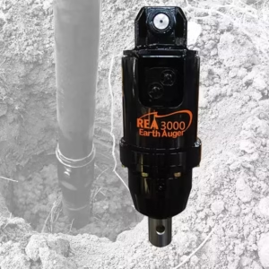
Earth Drill for mini excavator
Price range: £1,380.00 through £1,660.00Weight (Kg) 54 - 71Select options This product has multiple variants. The options may be chosen on the product page
A Grade
MAKE-Ray
Auger Attachments for Mini Excavators (1–5 Ton)
1. Review
This guide provides a complete technical overview of hydraulic auger attachments used on mini excavators for earth drilling, foundation work, fencing, and landscaping.
It covers:
- Design and function
- Hydraulic requirements
- Auger drive types
- Mounting configurations
- Bit and tooth selection
- Maintenance and inspection
- Troubleshooting and safety
2. OVERVIEW
A hydraulic auger is an excavator-mounted drilling attachment that converts hydraulic energy from the carrier machine into rotational torque for drilling holes into soil, clay, gravel, or light rock.
It consists of three primary systems:
- Drive Unit (Hydraulic Motor + Gearbox)
- Auger Shaft & Flight (Helical Drill)
- Mounting Bracket & Linkage Assembly
When connected to the excavator’s auxiliary hydraulic circuit, the auger can efficiently drill holes for posts, piles, poles, or tree planting.
3. WORKING PRINCIPLE
- Hydraulic oil from the excavator’s auxiliary line flows into the auger drive motor.
- The motor converts oil pressure and flow into rotational torque.
- The torque is transmitted through a planetary or direct-drive gearbox to the auger shaft.
- The auger flight (helix) rotates, cutting and lifting soil from the hole as it drills downward.
- The operator controls drilling direction, depth, and speed through the excavator’s hydraulic controls.
Torque (rotational force) and speed (RPM) vary depending on:
- Excavator flow rate (L/min)
- Hydraulic pressure (bar)
- Gearbox ratio
4. SYSTEM COMPONENTS
| Component | Description | Function |
|---|---|---|
| Hydraulic Motor | Orbital or piston type | Converts hydraulic flow into rotational motion. |
| Gearbox / Reduction Drive | Planetary or helical gear system | Multiplies torque and reduces speed for controlled drilling. |
| Output Shaft | Hex, square, or round interface | Connects gearbox to auger bit drive hub. |
| Auger Bit (Flight) | Helical drilling tool | Cuts and lifts soil. |
| Pilot & Teeth | Replaceable cutting tips | Penetrate and break soil or rock. |
| Mounting Bracket / Hitch | Adapter frame | Attaches auger drive to excavator arm. |
| Hydraulic Hoses & Couplers | Flexible high-pressure lines | Connect drive motor to excavator’s auxiliary ports. |
5. TYPES OF AUGER DRIVE SYSTEMS
5.1 PLANETARY GEAR DRIVE (Heavy-Duty Type)
 Description
High-torque, low-speed gearbox using multiple planetary gears.
Common in augers for 2–5 ton excavators.
 Advantages
- Extremely high torque output (up to 6,000 Nm).
- Suitable for hard soils and light rock.
- Long service life under heavy load.
 Considerations
- Slightly heavier and more costly than direct drive.
Typical Use
Post holes, piling, footings, dense soil or clay, and shale.
5.2 DIRECT DRIVE (Light-Duty Type)
Description
Motor output shaft connects directly to the auger shaft — no gearbox.
Used on 1–2 ton mini excavators and compact machines.
Advantages
- Lightweight and simple design.
- Lower cost and minimal maintenance.
Limitations
- Lower torque, unsuitable for heavy ground.
- Higher rotation speed — risk of stalling in dense material.
Typical Use
Soft soil, sand, or loam drilling for small posts or landscaping.
6. HYDRAULIC REQUIREMENTS (TYPICAL)
| Excavator Size | Flow Range | Pressure Range | Torque Output | Speed (RPM) |
|---|---|---|---|---|
| 1–2 Ton | 20–35 L/min | 100–150 bar | 800–1,500 Nm | 50–80 |
| 2–3 Ton | 30–50 L/min | 120–170 bar | 1,500–3,000 Nm | 40–70 |
| 3–5 Ton | 40–75 L/min | 150–200 bar | 3,000–6,000 Nm | 30–60 |
- Higher hydraulic pressure = more torque.
- Higher flow rate = more speed (RPM).
Always match auger model to excavator’s auxiliary specifications to avoid stalling or overheating.
7. MOUNTING CONFIGURATIONS
| Mount Type | Description | Advantages | Typical Use |
|---|---|---|---|
| Top-Mount (Direct Link) | Attaches directly to dipper arm via top bracket or quick coupler. | Maximum stability, ideal for vertical drilling. | General earth drilling, footings. |
| Tilt Hitch Mount | Bracket allows side-to-side tilt (±15–30°). | Drill on slopes or at angles. | Roadside or embankment work. |
| Swing Mount | Allows limited horizontal swing or offset. | Drill beside machine or in tight spaces. | Fence lines, close-to-wall work. |
| Cradle Mount / Frame Mount | Drive unit rests in a cradle when lifted. | Protects hoses and gearbox during travel. | Transport and alignment control. |
8. AUGER BIT SELECTION
8.1 Bit Diameter & Length
- Common sizes: 100 mm to 600 mm diameter.
- Standard lengths: 900–1,500 mm, extendable with drive extensions.
8.2 Bit Type by Ground Condition
| Ground Type | Recommended Bit | Features |
|---|---|---|
| Soft Soil / Sand | Earth Auger | Continuous flight, standard teeth. |
| Clay / Mixed | Combination Auger | Earth & tungsten-tipped teeth. |
| Gravel / Hardpan | Tungsten (Rock) Auger | Heavy-duty flights, carbide teeth. |
| Fractured Rock | Rock Auger with Pilot & Teeth | Bullet-style teeth for penetration. |
| Concrete / Asphalt | Core Barrel or Rock Drill | Heavy-duty pilot, slow speed drilling. |
8.3 Tooth & Pilot Maintenance
- Replace worn teeth before reaching half their original length.
- Inspect pilot bit for straightness and secure fit.
- Use correct grade bolts and torque settings when replacing teeth.
9. OPERATIONAL GUIDELINES
- Align vertically before engaging the auger.
- Apply steady down pressure — do not force the auger.
- Maintain constant rotation speed; avoid jerky movement.
- Lift the auger periodically to clear spoil from flights.
- Do not reverse rotation under heavy load — this damages the gearbox.
- Stop drilling if auger stalls; lift slightly and reapply pressure.
- Avoid spinning the auger at high speed without load (dry running).
- Keep clear of moving parts at all times.
10. INSPECTION & MAINTENANCE
10.1 Daily / Pre-Use
| Check | Purpose |
|---|---|
| Inspect hydraulic hoses and couplers for leaks or damage. | Prevent pressure loss and contamination. |
| Verify gearbox oil level (if applicable). | Maintain lubrication and cooling. |
| Check output shaft and drive hub for play. | Prevent spline wear. |
| Inspect auger teeth and pilot for wear. | Maintain cutting efficiency. |
| Ensure bolts and mounts are secure. | Prevent detachment under load. |
10.2 Periodic Maintenance (Every 250 Hours)
| Task | Description |
|---|---|
| Replace gearbox oil (planetary type). | |
| Check drive motor for seal leaks or shaft wear. | |
| Inspect mounting pins and bushes for ovality. | |
| Clean hydraulic couplers to prevent contamination. | |
| Torque all frame bolts to manufacturer specification. |
10.3 Annual Service
| Task | Description |
|---|---|
| Replace hydraulic hoses showing wear or cracking. | |
| Replace gearbox seals and O-rings. | |
| Check internal gears for pitting or spalling. | |
| Inspect drive shaft bearings. | |
| Perform hydraulic flow and pressure test. |
11. LUBRICATION
- Gearbox Oil: 80W-90 or EP90 gear oil (check manufacturer’s capacity).
- Grease Points: Use high-pressure lithium grease on cradle pivots and hitch pins.
- Change Interval: Every 250 operating hours or as per manufacturer’s specification.
12. SAFETY INFORMATION
- Only trained operators should use hydraulic augers.
- Do not exceed rated hydraulic flow or pressure.
- Keep all personnel clear of the auger flight during operation.
- Avoid overhead hazards — auger may swing when lifted.
- Never dig under the machine or exceed excavator stability limits.
- Always disengage hydraulics and relieve pressure before connecting or disconnecting hoses.
- Do not use damaged or worn bits.
- Wear PPE: gloves, safety boots, hard hat, and eye protection.
13. TROUBLESHOOTING GUIDE
| Symptom | Likely Cause | Corrective Action |
|---|---|---|
| Auger stalls easily | Hydraulic flow too low or ground too hard | Check excavator flow; reduce auger size or switch to rock bit. |
| Auger rotates slowly | Low flow or motor inefficiency | Inspect auxiliary circuit pressure & flow. |
| Excessive vibration | Bent auger flight or uneven teeth wear | Straighten shaft; replace teeth. |
| Oil leak from motor | Worn motor seals | Replace seals or service motor. |
| Auger doesn’t rotate | Blocked coupler or spool | Clean couplers; test control valve. |
| Gearbox overheating | Overfilled oil or insufficient lubrication | Drain to correct level; replace oil. |
14. STORAGE & TRANSPORT
| Condition | Instruction |
|---|---|
| Short-Term (Under 1 Month) | Store upright with auger bit removed and drive covered. |
| Long-Term Storage | Store indoors at 5–25 °C. Drain hydraulic oil if stored >6 months. Grease exposed metal. |
| Transport | Secure vertically in cradle or on stand; protect motor and couplers from impact. |
15. MAINTENANCE RECORD TEMPLATE
| Date | Technician | Hours | Model | Oil Checked | Observations | Action Taken |
|---|---|---|---|---|---|---|
16. TECHNICAL SUMMARY
| Category | Specification |
|---|---|
| Machine Compatibility | 1–5 Ton Mini Excavators |
| Drive Type | Direct Drive (Light), Planetary Drive (Heavy) |
| Torque Output | 800–6,000 Nm |
| Hydraulic Flow | 20–75 L/min |
| Hydraulic Pressure | 100–200 bar |
| Speed Range | 30–90 RPM |
| Bit Sizes | 100–600 mm standard |
| Ground Types | Soil, clay, gravel, light rock |
| Lubrication | EP90 gear oil + lithium grease |
| Maintenance Interval | 250-hour oil change, annual inspection |
| Noise Level | Typically <85 dB |
| Mounting Options | Top, Tilt, Swing, Cradle Mounts |
Hydraulic auger attachments transform mini excavators into versatile, precision drilling machines.
They deliver high torque and controlled drilling when matched correctly to the carrier’s hydraulic system.
Proper selection, maintenance, and alignment ensure maximum drilling efficiency, minimal wear, and long service life.