
-

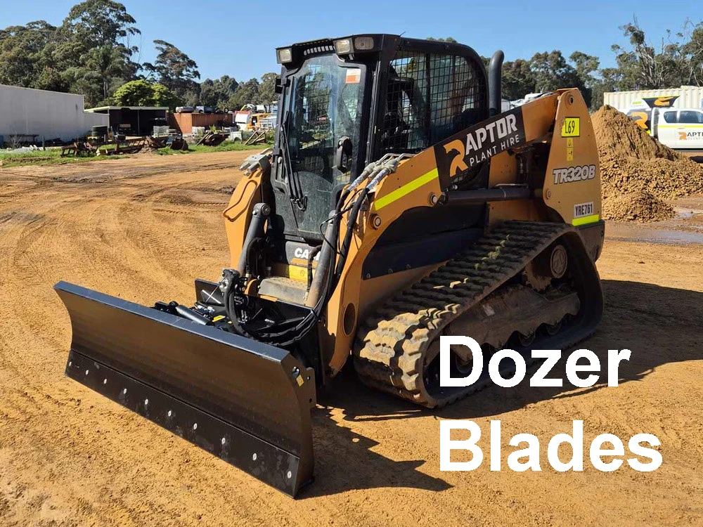
6 way Angle/Dozer Blade attachment for skid steer loader
Price range: £2,840.00 through £3,290.0060" - 84"Select options This product has multiple variants. The options may be chosen on the product page
Weight (Kg) 400 - 560
A Grade
MAKE-Sanxian -
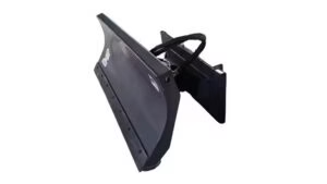
Angle/Dozer Blade Attachment for skid steer loader
Price range: £1,840.00 through £2,380.0060" - 84"Select options This product has multiple variants. The options may be chosen on the product page
Weight (Kg) 300 - 360
A Grade
MAKE-Sanxian
Technical Guide: Dozer Blade Attachments for Skid Steer Loaders
1. Overview
A dozer blade attachment transforms a skid steer loader into a compact, maneuverable earthmoving machine capable of grading, backfilling, and pushing materials like soil, gravel, or snow.
These attachments come in fixed, angle, and 6-way (PAT – Power Angle Tilt) configurations.
This guide provides full technical specifications and best practices for design, operation, and maintenance.
2. Functional Description
Purpose:
To allow skid steers to perform light to medium-duty dozing, grading, and site preparation work.
Key Capabilities:
- Material pushing and leveling.
- Precision grading with adjustable angles.
- Backfilling and trench closing.
- Snow removal and light debris clearing.
Mounting Interface:
Universal Skid Steer Quick Attach (SSQA) plate compliant with SAE J2513.
3. Types of Dozer Blades
| Type | Adjustment | Common Uses |
|---|---|---|
| Fixed Blade | No hydraulic movement | Basic pushing/backfill tasks |
| Angle Blade | Hydraulic or manual left/right (±30°) | Snow and grading |
| 6-Way Blade (PAT) | Hydraulic tilt, angle, and lift | Fine grading, contour shaping |
4. Technical Specifications
| Parameter | Typical Range / Specification |
|---|---|
| Blade Width | 72″ – 96″ (1.8 – 2.4 m) |
| Blade Height | 24″ – 30″ (0.6 – 0.76 m) |
| Blade Curvature Radius | 450–550 mm |
| Blade Cutting Edge | ½” × 6″ (12.7 × 152 mm) reversible, 1080 carbon steel |
| Side Skids (optional) | Adjustable wear shoes, AR400 steel |
| Operating Weight | 350 – 800 kg (depending on width and hydraulics) |
| Max Tilt | ±10° to ±15° |
| Max Angle | ±30° (left/right) |
| Hydraulic Pressure | 2000–3500 psi |
| Flow Requirement | 10–25 GPM |
| Rated Load Capacity | Equal or below skid steer ROC (Rated Operating Capacity) |
5. Structural Design
5.1 Blade Moldboard
- Constructed from AR400 or A572 Grade 50 steel for wear resistance.
- Formed curvature improves material rolling and reduces power loss.
- Welded stiffeners and ribs for rigidity.
5.2 Cutting Edge
- Bolt-on reversible edge for easy maintenance.
- 6–8 grade bolts (M16 × 40 mm) spaced evenly across the edge.
- Replaceable corner bits for heavy-use units.
5.3 A-frame & Pivot Mechanism
- Central pivot pin (Ø50–65 mm, 4140 hardened steel).
- Bronze or UHMW bushings with grease zerks.
- Reinforced A-frame arms welded from 75×75×6 mm structural tubing.
5.4 Tilt and Angle Cylinders
- Dual hydraulic cylinders (angle control) + single tilt cylinder (for PAT blades).
- Cylinders rated ≥1.5× system pressure.
- Pin-mounted with hardened bushings.
6. Hydraulic System Design
| Component | Specification |
|---|---|
| Cylinder Bore | 2.5″ – 3.0″ |
| Stroke | 8″ – 12″ |
| Pressure Rating | 3000 psi nominal |
| Hydraulic Couplers | ISO 16028 flat-face |
| Control Valve | 3-spool proportional valve (for 6-way) |
| Flow Range | 15–25 GPM (standard skid steer auxiliary circuit) |
Hydraulic Flow Routing Example (6-Way Blade):
Auxiliary OUT → Control Valve → Angle Cylinders
Auxiliary IN  → Return Line
Optional 3rd Function → Tilt Cylinder
Safety Features:
- Integrated pressure relief (3500 psi).
- Flow restrictors to prevent rapid or jerky movements.
- Color-coded couplers (A/B ports).
7. Mechanical Calculations (Example)
Blade Thrust Capacity
F=P×A×ηF = P \times A \times ηF=P×A×η
where
P=3000 psiP = 3000 \, psiP=3000psi, A=4.9 in2A = 4.9 \, in^2A=4.9in2 (2.5” bore), η=0.9η = 0.9η=0.9
→ F=13,230 lbF = 13,230 \, lbF=13,230lb (~5,990 kgf) per cylinder.
With two cylinders → Total lateral thrust ≈ 11,980 kgf.
Structural Stress
Check weld joints with: σ=FAweld<0.6×σyσ = \frac{F}{A_{weld}} < 0.6 × σ_yσ=AweldF<0.6×σy
where σy=345 MPaσ_y = 345 \, MPaσy=345MPa for A572 steel.
8. Manufacturing Specifications
| Component | Material | Thickness | Process |
|---|---|---|---|
| Moldboard | AR400 | 6–10 mm | Press-formed + MIG welded |
| Cutting Edge | 1080 high-carbon | 12–16 mm | Bolted |
| Frame Tubing | ASTM A500 Gr.B | 6 mm wall | MIG welded |
| Pivot Pin | 4140 HT | Ø50–65 mm | Machined & hardened |
| Gussets | A36 plate | 8 mm | Laser-cut |
Welding Requirements:
- AWS D1.1 compliant.
- Minimum fillet weld: 6 mm continuous.
- 100% visual inspection + 10% magnetic particle test.
9. Controls and Operator Interface
- Operated via skid steer auxiliary hydraulic controls.
- For 6-way models, use a 3-function joystick or electro-hydraulic proportional control.
- Optional in-cab float mode for grading (allows blade to follow ground contour).
Optional Electronics:
- Laser or GPS grade control interface (Trimble/Topcon compatible).
- Blade position feedback sensors.
10. Mounting Interface
Standard:
SAE J2513 Skid Steer Quick Attach (Universal Mount).
Attachment Steps:
- Drive forward to engage lower plate hooks.
- Tilt coupler to seat top plate.
- Engage locking levers (manual or hydraulic).
- Connect hydraulic couplers (match flow direction).
- Perform function test before operation.
11. Testing and Validation
| Test | Purpose | Procedure |
|---|---|---|
| Static Load Test | Structural integrity | Apply 1.5× rated push load for 10 min |
| Functional Test | Hydraulic operation | Cycle cylinders under load |
| Wear Test | Edge durability | 50 hr continuous grading |
| Field Validation | Real-use simulation | Operate in soil, gravel, snow conditions |
12. Maintenance and Service
| Interval | Task |
|---|---|
| Daily | Check cutting edge, clean pivot pins, inspect hoses |
| Weekly | Grease all bushings (Lithium EP2), inspect hydraulic fittings |
| Monthly | Check welds, repaint worn surfaces, tighten bolts |
| 500 hrs | Replace cutting edge, inspect cylinder seals |
| Annually | Pressure test hydraulic system, replace worn bushings |
13. Safety and Compliance
- Always lower blade to ground before exiting cab.
- Use blade float mode when fine grading to prevent gouging.
- Maintain a safe distance from personnel during operation.
- Ensure attachment matches the skid steer’s hydraulic and weight capacity.
- Follow OSHA 1926.602(a) and ISO 6018 guidelines for attachment safety.
14. Example Dimensional Reference (for 84” 6-way blade)
| Dimension | Value (mm) |
|---|---|
| Overall Width | 2130 |
| Height | 660 |
| Blade Radius | 500 |
| Cutting Edge | 152 × 12.7 |
| Tilt Range | ±12° |
| Angle Range | ±30° |
| Weight | 520 kg |
15. Optional Accessories
- Replaceable Wear Edges
- Snow Deflector Kit
- Skid Shoes
- Electric-over-Hydraulic Control Kit
- Grade Control System Interface
- High-Visibility Moldboard Window
16. Example Manufacturing Process Flow
- CAD Design & Simulation – SolidWorks FEA for stress/deflection.
- Material Cutting – Laser/plasma cut structural plates.
- Forming – Press brake for moldboard curvature.
- Fixture Welding – Robotic or jig-assisted MIG.
- Machining – Pin holes, pivot mounts.
- Coating – Powder coat (70–90 µm thickness).
- Assembly – Cylinder install, bolt-on edges.
- Testing & QC – Dimensional and functional validation.
17. Documentation & Labeling
Each unit must include:
- Serial number and manufacturing batch code.
- Rated hydraulic pressure and flow.
- Safety decals and instructions.
- Operator’s and service manual.