
-
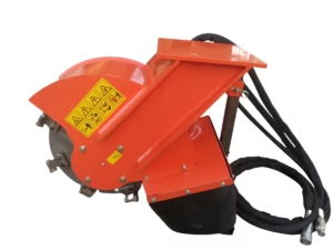
Stump Grinder Attachment for mini excavator
Price range: £1,790.00 through £1,940.00
Weight (Kg) 180 – 192Select options
Professional Grade
MAKE-Contract
This product has multiple variants. The options may be chosen on the product page
1. INTRODUCTION
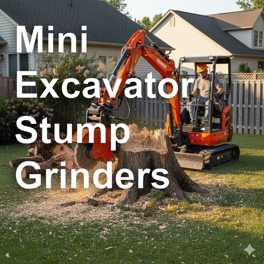
A stump grinder attachment allows a mini or compact excavator to efficiently remove tree stumps by grinding them into mulch.
The attachment replaces the excavator’s bucket and uses the machine’s hydraulic auxiliary circuit to drive a rotating cutting wheel fitted with tungsten-carbide teeth.
Typical Applications
- Land and site clearance
- Landscaping and vegetation control
- Forestry and urban tree management
- Utility and trenching preparation
- Work in restricted or confined access areas
2. EXCAVATOR COMPATIBILITY
| Specification | Typical Range (1–5 Ton Machines) | Notes |
|---|---|---|
| Excavator Operating Weight | 1,000 – 5,000 kg | Mini and compact class |
| Auxiliary Hydraulic Flow | 25 – 80 L/min | Determines wheel speed |
| Hydraulic Pressure | 150 – 230 bar | Determines cutting torque |
| Auxiliary Circuit Type | Single or dual flow | Typically hammer or auger circuit |
| Return Line | Required | Must return directly to tank (<5 bar back pressure) |
| Electrical Supply (optional) | 12V DC | For solenoid valves or hydraulic tilt systems |
| Coupler / Mount Type | Pin-on or quick coupler (see Section 4) | Must match excavator arm geometry |
3. TYPES OF STUMP GRINDERS
Stump grinder attachments are categorized by drive mechanism and mobility features. The correct type depends on excavator size, hydraulic capacity, and application.
3.1 Direct-Drive Grinders
- Description: Hydraulic motor drives wheel directly via its shaft.
- Advantages: Compact, minimal maintenance, lightweight.
- Ideal For: 1–3 ton excavators, landscaping use.
- Limitations: Slightly less torque for large hardwood stumps.
3.2 Gear-Drive Grinders
- Description: Motor drives gearbox to increase torque.
- Advantages: High torque, stable cutting under heavy load.
- Ideal For: 3–5 ton excavators and forestry use.
- Limitations: Heavier and requires gearbox oil maintenance.
3.3 Belt-Drive Grinders
- Description: Power transmitted via V-belt or toothed belt.
- Advantages: Smooth operation, protects motor from shock loads.
- Ideal For: Mixed-duty applications, 2–4 ton machines.
- Limitations: Requires periodic belt tensioning.
3.4 Swing-Head Grinders
- Description: Cutting wheel mounted on a frame that swings hydraulically or mechanically side-to-side.
- Advantages: Faster material removal, reduced excavator repositioning.
- Ideal For: 3–5 ton excavators with auxiliary swing circuit.
- Limitations: More hydraulic complexity and weight.
3.5 Fixed-Head Grinders
- Description: The head is rigidly mounted; the operator sweeps with the excavator arm.
- Advantages: Simple, light, and cost-effective.
- Ideal For: Small excavators (1–3 ton).
- Limitations: Slower on large stumps; requires more operator movement.
3.6 Tilt-Head Grinders
- Description: Includes manual or hydraulic tilt mechanism for angled grinding.
- Advantages: Ideal for uneven terrain and sloped work sites.
- Ideal For: 2–5 ton excavators.
- Limitations: Slightly heavier and more expensive than fixed head.
4. MOUNT TYPES
Selecting the correct mount or coupler system ensures compatibility, quick attachment changes, and safe operation.
Mounts vary depending on excavator brand, size, and coupler style.
| Mount Type | Description | Compatible Excavator Sizes | Notes |
|---|---|---|---|
| Pin-On Mount | Standard dual-pin connection directly to dipper arm and linkage. | 1–5 ton | Simple, secure, low cost; slower to change. |
| S-Series (S30, S40, S45) | Scandinavian-style quick coupler with dual wedge lock. | 1.5–5 ton | Common in Europe; precise, quick change. |
| CW05 / CW10 | Caterpillar/Hitachi-type wedge-lock coupler. | 2–5 ton | Durable and widely supported. |
| Klac System (Klac Mini/Medium) | French automatic coupler with spring latch. | 1–4 ton | Compact design, easy changeover. |
| Wain-Roy / Manual Quick Coupler | Lever-actuated manual coupler plate. | 2–5 ton | Quick, no hydraulics; requires manual engagement. |
| Custom Plate Mount | Welded adapter plate for unique or older machines. | 1–5 ton | Used for special projects or OEM integration. |
Mounting Guidelines
- Always match pin diameter, pin spacing, and pin center-to-center distance to excavator specifications.
- Confirm the pin offset to maintain correct grinder geometry and cutting angle.
- Ensure hydraulic hoses are routed safely within the arm’s movement arc.
- Use locking pins or safety clips on manual couplers to prevent accidental release.
5. DESIGN AND COMPONENTS
| Component | Description | Material / Specification |
|---|---|---|
| Cutting Wheel | Hardened steel disk that grinds wood. | Ø350–500 mm, heat-treated |
| Cutting Teeth | Replaceable, carbide-tipped teeth in spiral or alternating layout. | Tungsten carbide, 12–24 per wheel |
| Hydraulic Motor | Converts hydraulic flow into rotation. | Gerotor, gear, or piston motor |
| Drive System | Transfers torque to wheel. | Direct, gear, or belt drive |
| Guard Housing / Shroud | Shields operator and excavator from debris. | 5–8 mm steel with rubber curtain |
| Bearing Support | Carries radial and axial load from wheel. | Double-row sealed bearings |
| Mounting Frame | Connects grinder to coupler or pins. | Welded structural steel |
| Hydraulic Hoses | Supply and return circuits. | 250+ bar rated, flat-face couplers |
| Optional Tilt / Swing Frame | Allows adjustable grinding angles. | Manual or hydraulic operation |
6. HYDRAULIC INTEGRATION
6.1 Circuit Configuration
[Excavator AUX Pressure Port] → [Grinder IN Port]
[Grinder OUT Port] → [Excavator Return/Tank Port]
[Case Drain Port]* → [Direct Tank Return]
(Only required for high-speed or piston motors.)
6.2 Typical Hydraulic Parameters
| Parameter | Range | Function |
|---|---|---|
| Flow | 25–80 L/min | Determines wheel speed |
| Pressure | 170–230 bar | Determines torque |
| Back Pressure | < 5 bar | Prevents seal/bearing failure |
| Oil Type | ISO VG46 or per excavator manual | Cleanliness critical (ISO 18/16/13) |
⚙️ Adjust excavator’s auxiliary flow control to match grinder rating for optimal torque and cutting performance.
7. INSTALLATION PROCEDURE
- Preparation
- Park excavator on level ground.
- Release hydraulic pressure and clean all couplers.
- Mounting
- Attach grinder to coupler or pin frame.
- Verify secure locking of coupler pins.
- Hydraulic Connection
- Connect pressure and return hoses.
- Ensure rotation direction matches manufacturer’s diagram.
- Connect case drain (if applicable).
- Testing
- Engage AUX circuit at low flow.
- Check for leaks and smooth rotation.
- Gradually increase to full speed.
8. OPERATIONAL PARAMETERS
| Parameter | Recommended Range | Notes |
|---|---|---|
| Max Stump Diameter | Up to 400 mm | Larger stumps require multi-pass approach |
| Cut Depth per Pass | 25–50 mm | Avoid overloading motor |
| Wheel Speed | 1,000–1,800 rpm | Adjust per stump density |
| Sub-Ground Depth | 100–150 mm | Ensures full stump removal |
| Sweeping Motion | Side-to-side | Maintains control and efficiency |
9. SAFETY PRECAUTIONS
| Hazard | Prevention |
|---|---|
| Flying debris | Maintain 10 m exclusion zone, use deflector curtain. |
| Hydraulic pressure | Never disconnect under pressure; wear gloves. |
| Noise | Use hearing protection (>90 dB typical). |
| Vibration | Inspect teeth regularly and rebalance if needed. |
| Machine stability | Operate on level surface, avoid overextension. |
10. MAINTENANCE SCHEDULE
| Interval | Task | Notes |
|---|---|---|
| Daily | Inspect teeth, hoses, and guards. | Replace damaged components. |
| Every 10 Hours | Grease bearings and pivots. | Use lithium EP grease. |
| Every 50 Hours | Retorque teeth (80–100 Nm). | Use thread-lock compound. |
| Every 100 Hours | Check hydraulic seals and fittings. | Replace if leaking. |
| Every 250 Hours | Inspect bearings and balance. | Replace as required. |
| Annually | Overhaul drive system, repaint frame. | Conduct in workshop. |
11. TROUBLESHOOTING
| Symptom | Cause | Remedy |
|---|---|---|
| Slow rotation | Low flow or pressure | Check AUX circuit or restrictors |
| Overheating | High back pressure | Inspect return line routing |
| Excessive vibration | Missing or dull teeth | Replace and rebalance |
| Poor cutting | Incorrect RPM | Adjust flow or pressure |
| Oil leak | Worn seals | Replace seal kit |
12. OPTIONAL FEATURES & ACCESSORIES
- Hydraulic tilt or swing frames
- Flow control block (for flow limitation)
- Case drain kits (for piston-type motors)
- Quick coupler adapters (S-series, CW, Klac, pin-on)
- Debris deflector curtains
- Replacement carbide tooth kits
- Hydraulic flow and pressure test kit
13. STORAGE & TRANSPORT
- Clean and grease exposed metal surfaces.
- Store in a dry, covered area.
- Fit dust caps to hydraulic couplers.
- Rest wheel on timber block to protect teeth.
- Secure attachment with proper tie-downs during transport.
14. SUMMARY
| Feature | Benefit |
|---|---|
| Multiple drive types | Suited for various excavator sizes and workloads |
| Universal mount options | Compatible with major coupler systems |
| Replaceable carbide teeth | Long service life and easy maintenance |
| Compact, efficient design | Ideal for 1–5 ton excavators |
| Hydraulic drive | Powerful and reliable cutting performance |