
Pallet Fork Attachments for Skid Steer Loaders (1–5 Ton)
1. PURPOSE
This guide provides a technical and operational reference for pallet fork attachments designed for skid steer loaders.
It explains:
- Design and components
- Fork types and capacity classes
- Operating principles
- Maintenance and inspection routines
- Troubleshooting and safety standards
The aim is to help operators, technicians, and supervisors ensure safe handling, proper load distribution, and extended service life.
2. SYSTEM OVERVIEW
A pallet fork attachment enables a skid steer loader to lift, transport, and stack palletized or irregular materials safely and efficiently.
It mounts to the machine using a universal quick-attach system, allowing fast interchangeability between attachments.
Unlike hydraulic tools, pallet forks operate mechanically, controlled by the loader’s lift and tilt functions.
Optional hydraulic variants exist for side-shift or grapple configurations.
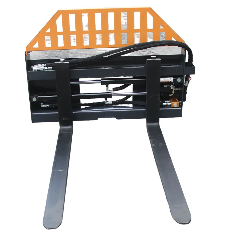
3. DESIGN & CONSTRUCTION
| Component | Description | Function |
|---|---|---|
| Fork Frame / Carriage | Heavy-duty welded steel frame with quick-attach plate. | Supports fork tines and connects to loader arms. |
| Fork Tines | Forged or cast steel arms extending forward. | Engage and lift pallets or materials. |
| Backrest / Load Guard | Vertical grid or plate behind carriage. | Prevents load from falling toward operator. |
| Carriage Bar / Rail | Horizontal mounting bar. | Allows tine adjustment along frame width. |
| Fork Locking Pins | Spring-loaded or manual retainers. | Secure tines in position during operation. |
| Mounting Plate | Universal quick-attach interface. | Provides secure coupling to loader. |
| Hydraulic Side-Shift / Grapple (optional) | Auxiliary hydraulic mechanism. | Enables tine shift or clamping movement. |
Standard skid steer fork frames are rated between 1,000 kg – 3,000 kg, depending on tine length and class.
4. TYPES OF PALLET FORK ATTACHMENTS
| Type | Description | Key Features | Common Applications |
|---|---|---|---|
| Standard Fork Frame | Fixed frame with manually adjustable tines. | Simple, durable, lightweight. | General pallet handling, construction materials. |
| Heavy-Duty Fork Frame | Reinforced carriage and thicker tines. | Increased load rating, taller backrest. | Masonry, lumber, concrete block handling. |
| Hydraulic Side-Shift Fork | Hydraulic cylinder shifts tines left/right. | Precise pallet alignment. | Warehousing, narrow spaces, logistics. |
| Walk-Through Frame | Open top and center design. | Better operator visibility and access. | Landscaping, nurseries, small pallet work. |
| Grapple Fork Attachment | Includes hydraulic top clamp. | Secures irregular loads like logs or debris. | Construction, waste handling, forestry. |
| Adjustable Mini-Frame Fork | Narrow carriage for compact skid steers. | Reduced weight and width. | Residential or garden workspaces. |
5. FORK CLASSIFICATION & RATINGS
Pallet forks follow ISO 2328 / ITA Class standards for carriage height and load capacity.
| Class | Capacity (per pair) | Carriage Height | Common Use |
|---|---|---|---|
| Class II | Up to 2,500 kg (5,500 lb) | 406 mm (16 in) | Standard skid steers |
| Class III | Up to 5,000 kg (11,000 lb) | 508 mm (20 in) | Large frame loaders |
Typical Fork Specifications
| Fork Length | Width | Thickness | Capacity per Pair | Frame Weight | Recommended Use |
|---|---|---|---|---|---|
| 900 mm (36 in) | 100 mm | 35 mm | 1,000 kg | 80 kg | Light materials, pallets |
| 1,067 mm (42 in) | 100 mm | 38 mm | 1,800 kg | 95 kg | General construction use |
| 1,220 mm (48 in) | 100 mm | 40 mm | 2,200 kg | 105 kg | Heavy pallets, lumber |
| 1,370 mm (54 in) | 120 mm | 45 mm | 2,700 kg | 115 kg | Masonry and stone yards |
6. OPERATION PRINCIPLES
6.1 Basic Function
The fork frame tilts and lifts using the skid steer’s boom and tilt cylinders.
Fork tines slide horizontally on the carriage rail to accommodate various load widths.
6.2 Load Positioning
- Forks must be evenly spaced and parallel.
- The load center should be 50% of fork length or less.
- Keep the load as close to the carriage as possible for maximum stability.
7. HYDRAULIC OPTIONS (IF EQUIPPED)
Hydraulic fork variants use the skid steer’s auxiliary circuit to enable side shift or grapple functions.
| Feature | Hydraulic Flow (L/min) | Pressure (bar) | Cylinder Bore | Application |
|---|---|---|---|---|
| Side-Shift Frame | 20–40 | 100–140 | 40–50 mm | Align pallets without repositioning loader. |
| Grapple Clamp Fork | 25–45 | 120–160 | 50–60 mm | Secure loose materials, logs, debris. |
Always check flow direction before connecting hoses to prevent cylinder seal damage.
8. LOAD STABILITY & CENTER OF GRAVITY
| Load Placement | Effect | Risk |
|---|---|---|
| Load fully back on forks | Optimum balance | Stable |
| Load halfway forward | Shifts center of gravity outward | Possible tipping |
| Unevenly loaded forks | Unbalanced side load | Frame twist or roll hazard |
Rule: Load center (D) ≤ 0.5 × fork length (L).
Example: For 1,200 mm forks, load center ≤ 600 mm.
9. OPERATIONAL GUIDELINES
- Pre-Operation Inspection:
- Check forks for cracks, bends, and wear.
- Ensure frame locking pins engage fully.
- Verify backrest integrity.
- Operation:
- Approach pallet slowly and level.
- Insert forks completely under the load.
- Tilt the mast back 10–15° for stability.
- Keep load low while traveling (< 30 cm above ground).
- Avoid side slopes or uneven terrain.
- Stacking / Unloading:
- Stop loader completely before raising.
- Align vertically with stack.
- Lower load gently to avoid impact stress.
10. INSPECTION & MAINTENANCE
10.1 Daily Checks
| Check | Purpose |
|---|---|
| Fork tines for cracks or deflection. | Identify fatigue damage. |
| Carriage rail and pins. | Ensure tines adjust smoothly. |
| Quick-attach pins. | Maintain secure coupling. |
| Rust, debris, or paint wear. | Prevent slippage or corrosion. |
10.2 250-Hour / Periodic Service
| Task | Description |
|---|---|
| Lubricate carriage bar and locking pins. | |
| Inspect all welds and frame joints for cracks. | |
| Re-torque backrest bolts. | |
| Check fork tip alignment (within 3 mm). | |
| Repaint worn surfaces. |
10.3 Annual / Overhaul
| Task | Description |
|---|---|
| Magnetic or dye-penetrant crack test. | |
| Replace bent or deformed forks. | |
| Replace carriage bushings or locking pins. | |
| Verify fork angle and mount tolerances. |
11. TROUBLESHOOTING
| Symptom | Likely Cause | Corrective Action |
|---|---|---|
| Forks difficult to slide | Rust or debris on rail | Clean and grease bar. |
| Forks misaligned | Bent carriage or rails | Repair or replace frame. |
| Load unstable | Uneven spacing or off-center load | Adjust forks and reload. |
| Quick-attach not locking | Debris or worn pin | Clean, lubricate, or replace. |
| Fork bending | Overload or side loading | Reduce load; replace fork. |
12. SAFETY INFORMATION
- Never exceed rated load capacity of forks or loader.
- Keep load low while moving; never travel with raised forks.
- Do not lift or transport people using pallet forks.
- Maintain a safe 10 m exclusion zone for bystanders.
- Never use forks to pry, push, or dig.
- Avoid side loads — lift straight and level.
- Lower forks to the ground before leaving the cab.
- Wear appropriate PPE (steel-toe boots, gloves, high-vis clothing).
13. STORAGE & TRANSPORT
| Condition | Instruction |
|---|---|
| Short-Term | Lower to ground, forks level, clean of debris. |
| Long-Term | Grease pins, oil exposed steel, and store indoors. |
| Transport | Secure attachment with chains through carriage frame. |
14. MAINTENANCE RECORD TEMPLATE
| Date | Technician | Hours | Model | Observations | Action Taken |
|---|---|---|---|---|---|
15. TECHNICAL SUMMARY
| Category | Specification |
|---|---|
| Attachment Type | Pallet Fork (Standard, Heavy-Duty, Hydraulic, Grapple) |
| Machine Type | Skid Steer Loader (1–5 Ton) |
| Mounting System | Universal Skid Steer Quick-Attach |
| Fork Class | Class II or III (ISO 2328) |
| Fork Length Range | 900–1,370 mm |
| Rated Capacity | 1,000–3,000 kg (pair) |
| Frame Weight | 80–140 kg |
| Tilt Angle (Loader-Dependent) | ±15° typical |
| Lubrication | Grease carriage bar every 50 hours |
| Service Interval | 250-hour inspection; annual crack test |
| Standards Compliance | ISO 2328 / ISO 2330 / EN ISO 12100 |
 Pallet fork attachments transform skid steer loaders into efficient, compact lifting machines.
Correct fork alignment, balanced loads, and routine inspections ensure maximum operator safety, precise handling, and long service life — whether on construction sites, farms, or warehouses.