skidsteer.uk

Blade Width
1100 mm
CLASS*Professional Grade
Weight 120 Kg
Blade Width
1100
CLASS*A Grade/Hire Grade
Weight

Technical Guide: Dozer Blade Attachments for Mini Skid Steer Loaders


1. Introduction

A dozer blade attachment converts a mini skid steer loader into a compact, multipurpose earthmoving tool. It enables efficient grading, levelling, backfilling, contour shaping, and light dozing in confined spaces such as residential lots, landscaping projects, or utility work zones.


2. Overview of Dozer Blade Attachments

2.1. Primary Functions

  • Grading soil, gravel, or aggregate
  • Leveling and smoothing surfaces
  • Backfilling trenches or foundations
  • Pushing light debris or snow
  • Contour and finish grading

2.2. Common Blade Types

Blade TypeDescriptionTypical Use
Straight Blade (S-Blade)Fixed angle; pushes material forwardGrading, backfilling
Angling Blade (A-Blade)Angles left or right, manual or hydraulicDitch shaping, snow removal
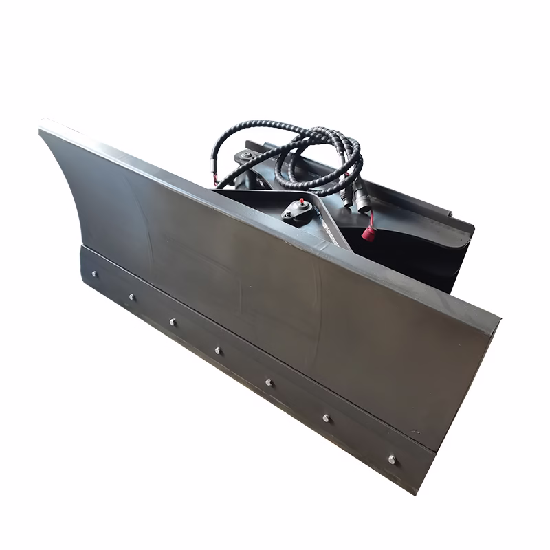
6-Way / Power-Tilt BladeAngles and tilts hydraulicallyContour or slope grading
V-Blade / Snow BladeAdjustable wings forming a V or scoopSnow or loose material pushing

3. Design and Construction

3.1. Key Components

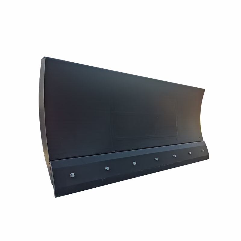
  • Moldboard: Curved steel face, generally 1.2–2.1 metres wide for mini skid steers.
  • Cutting Edge: Replaceable 12–13 mm thick hardened steel edge bolted along the bottom.
  • Push Frame: Structural support linking the blade to the quick-attach plate.
  • Angle/Tilt Cylinders: Hydraulic cylinders controlling movement.
  • Quick-Attach Plate: Standard mounting interface for mini skid steers.
  • Hydraulic Hoses & Couplers: Connect to the loader’s auxiliary hydraulic circuit.
  • Trip Springs (if equipped): Allow the blade to tip forward upon impact to prevent damage.

3.2. Materials

  • Moldboard: 4.8–6.4 mm thick mild or abrasion-resistant steel.
  • Cutting Edge: 12–13 mm hardened steel (400–500 Brinell hardness).
  • Frame: Box-section structural steel tubing, typically 50×75 mm or 50×100 mm.

4. Hydraulic System Integration

4.1. Hydraulic Requirements

FunctionOperating PressureFlow RateNotes
Angling17–21 MPa23–45 L/minUses loader’s auxiliary hydraulics
Tilting (6-way)17–21 MPa23–45 L/minSeparate or shared circuit
Float ModeLoader controlAllows blade to follow ground contours

4.2. Hydraulic Connection Procedure

  1. Park on level ground and relieve hydraulic pressure.
  2. Attach the blade to the quick-attach plate and lock securely.
  3. Clean and connect hydraulic couplers.
  4. Start the loader and engage hydraulics to check for leaks.
  5. Cycle the cylinders through full travel and confirm float operation.

5. Operational Setup and Adjustment

5.1. Pre-Use Inspection

  • Check for cracks, wear, or loose bolts.
  • Inspect cutting edge condition.
  • Ensure hoses and fittings are secure and leak-free.
  • Verify float and control lever function.

5.2. Adjustments

  • Blade Angle: ±25–30°.
  • Blade Tilt (6-Way): ±10–15°.
  • Height / Float: Engage loader’s float mode for consistent surface tracking.

6. Operating Techniques

6.1. Straight Dozing

  • Lower blade to desired cutting depth (10–25 mm per pass).
  • Push material steadily at low speed.
  • Overlap passes for a smooth finish.

6.2. Angled Grading

  • Angle the blade to windrow material to one side.
  • Maintain even speed and consistent hydraulic control.

6.3. Slope or Contour Work

  • Tilt blade 5–10°.
  • Work uphill or downhill for even slope formation.

6.4. Backfilling

  • Keep blade straight; use float mode.
  • Push light material in shallow passes.
  • Avoid aggressive impact loading.

7. Maintenance and Service

7.1. Daily

  • Clean soil and debris from blade and joints.
  • Inspect hydraulic hoses for wear or leaks.
  • Lubricate all pivot pins and cylinder ends.

7.2. Weekly

  • Tighten hardware, especially the cutting edge bolts.
  • Inspect for cracks or bent components.
  • Check cylinder operation and hydraulic oil clarity.

7.3. Periodic (Every 250 Hours)

  • Inspect cylinder rods and seals.
  • Repaint or coat exposed steel surfaces.
  • Replace worn edges or damaged fasteners.

8. Safety Precautions

  • Do not exceed the loader’s rated lifting or hydraulic capacity.
  • Keep people and obstacles clear of the operating zone.
  • Lower the blade fully when parked.
  • Relieve hydraulic pressure before disconnecting hoses.
  • Avoid travelling quickly with the blade lowered.

9. Troubleshooting Guide

IssuePossible CauseRecommended Action
Blade won’t moveReversed couplers or low hydraulic pressureVerify hose orientation and system pressure
Uneven gradingBlade not level or float not engagedAdjust tilt and enable float
Blade driftsInternal cylinder leakInspect and rebuild or replace seals
Excessive vibrationWorn or loose cutting edgeTighten bolts or replace edge

10. Typical Specifications

SpecificationRange
Blade Width1.2–2.1 m
Blade Height460–610 mm
Attachment Weight115–225 kg
Angling Range±25–30°
Tilt Range (6-way)±10–15°
Hydraulic Pressure17–21 MPa
Hydraulic Flow23–45 L/min

11. Torque Reference for Cutting Edge Bolts

Bolt SizeTorque (N·m)
M12100
M16200
M20350

12. Common Hydraulic Coupler Sizes

  • 10 mm flat-face (ISO 16028): Standard for most mini skid steers.
  • Always match coupler flow and pressure rating to the loader’s auxiliary system.